Step 5: Priority List of Major Maintenance
Update the priority list of major maintenance periodically at the national level,at an interval of 2 to 3 years by engaging a consultant.The update to be based on data collected in routine inspection and principal inspection, using inspection instruments. The update shall be formalised by Bridge Project. Division shall collect the updated data from the Bridge Project periodically
2.2 Routine inspections
This type of inspection will be undertaken at least once a year by staff from the Maintenance Divisions. It is essentially a visual inspection, possibly supplemented by a few simple measurements. It should generally be undertaken at a time of low water so that substructures, the river bed and any bed protection can be inspected. The Routine Inspection is very important. The results of this inspection enable the Divisions to plan the annual bridge maintenance work. Timely inspection and preventative maintenance protect the National assets of Nepal. Simple access equipment, such as a ladder, will be used from time to time to reach less accessible parts. Binoculars can be used to inspect areas beyond the reach of a ladder. The more inaccessible parts are usually left to more detailed Principal Inspections, unless a problem is suspected. In this case additional access equipment may be called for.
Routine inspections include adjacent earthworks or waterways, damage or other changes to which could affect the stability of the structure. River banks in the vicinity are examined for evidence of scour or for other conditions, such as deposition of debris, which could cause problems.
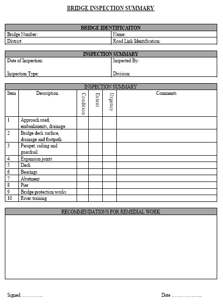
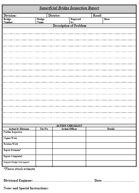
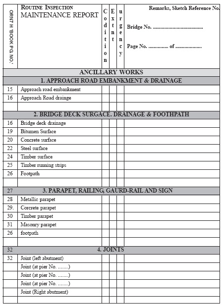
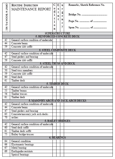
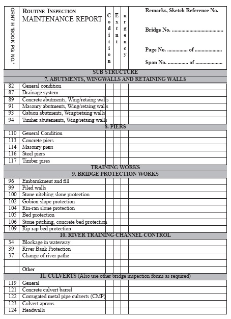
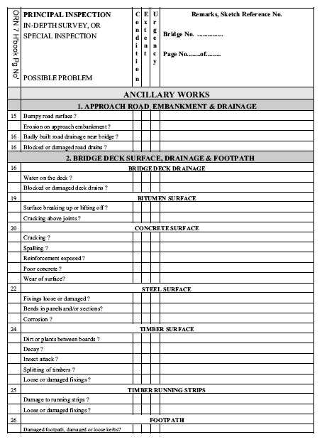
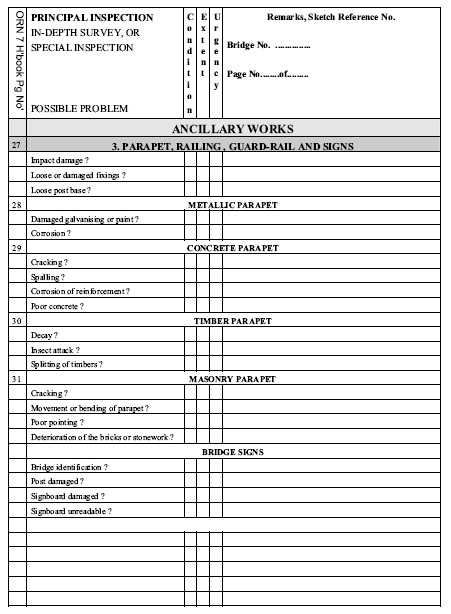
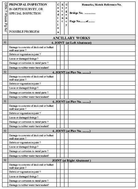
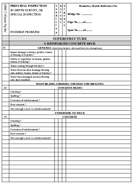
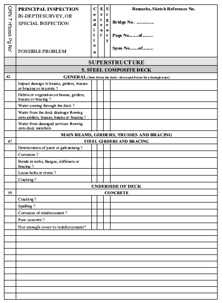
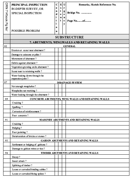
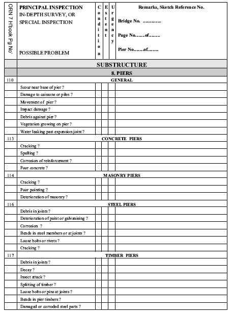
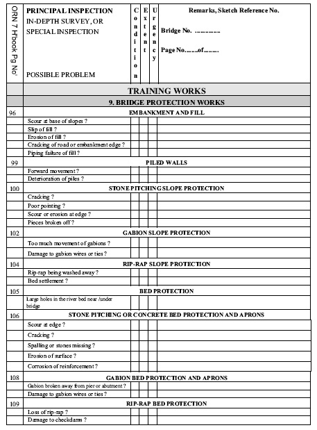
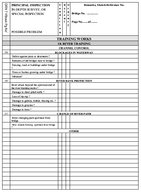
Report forms for the Routine Inspection are given in Appendix C. The forms comprise three pages which summarise the condition of the bridge component elements, recording where maintenance work is required. The components include associated works, such as embankments and bridge protection works. Not all of the forms are used, this depends on the structure that is being inspected. Site sketches, photographs and notes augment the report forms. Two other forms are included with the Routine Inspection Forms:
- Bridge Inspection Report Form - Bridge Identification
- Bridge Inspection Summary.
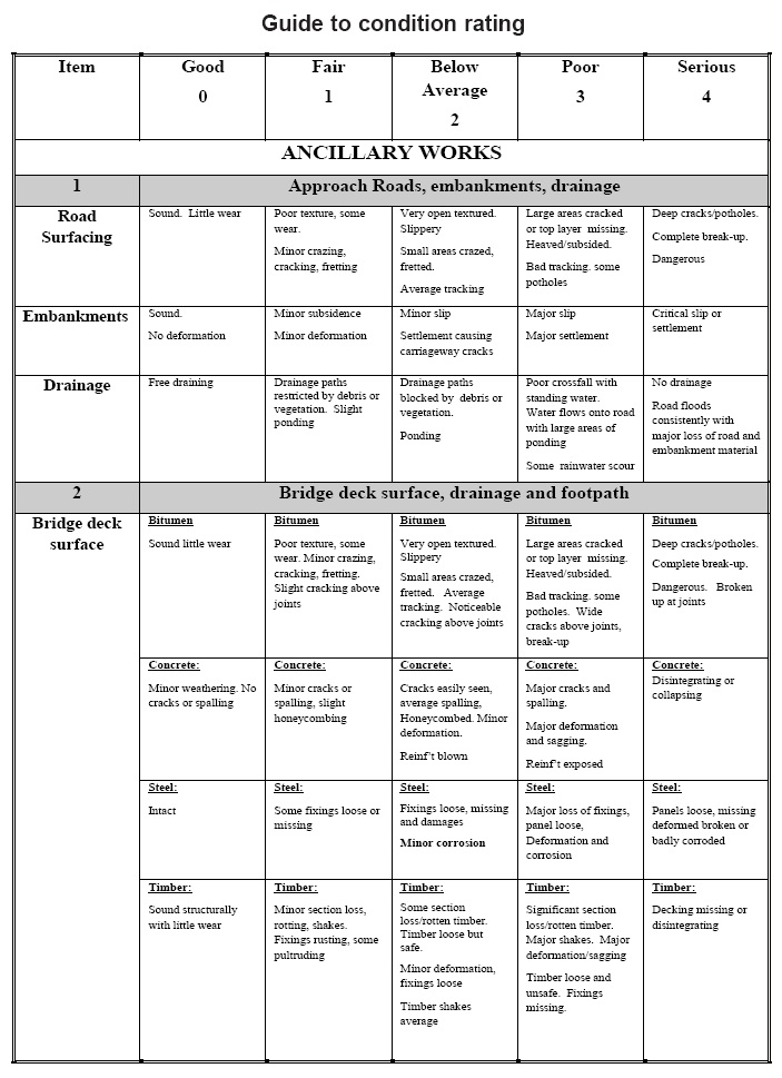
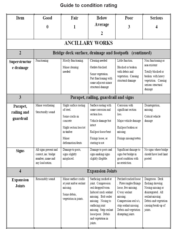
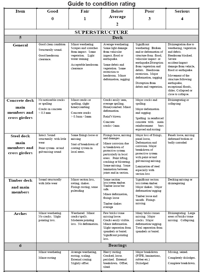
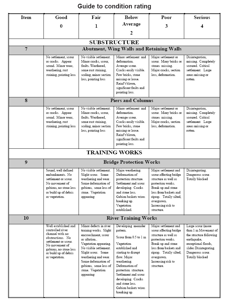
The Department’s standard rating system for bridges is used for Routine Inspections. This ensures that a uniform system for inspection is applied throughout Nepal, and when staff transfer between Regions and Divisions it is not necessary to learn a new system. The common rating system helps all Departmental staff to perceive the bridge condition without actually seeing the bridge. The Bridge Unit is available to support all inspections. The contents of the main body of this manual describe the requirements for this type of inspection.
Inspection Forms Appendix C, pages71 to 93,

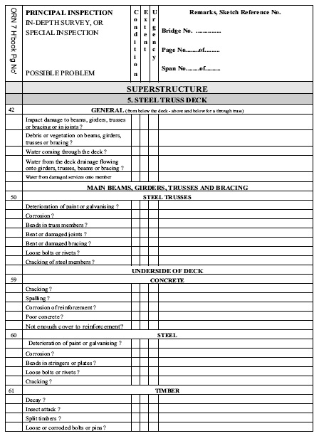
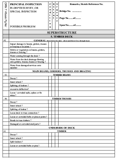
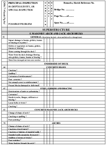
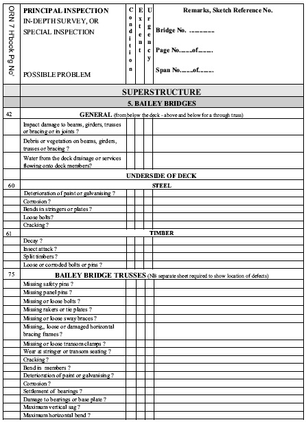

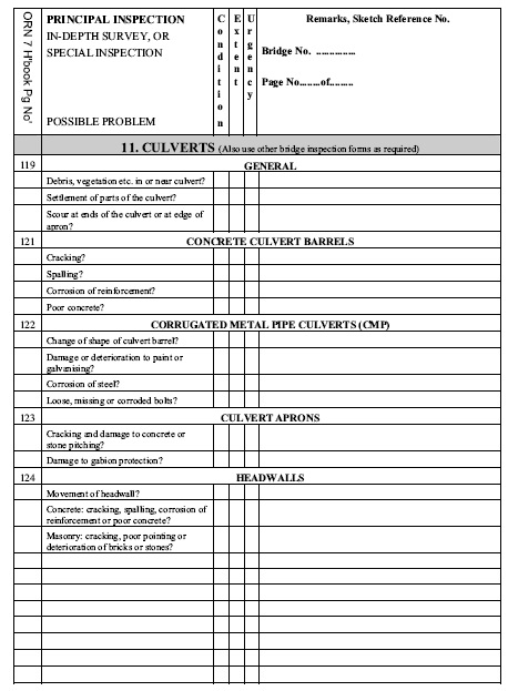
Rating Guide Appendix D pages 95 to 101 and Testing, Method of Testing, Special Testing Equipment,
| Condition Rating |
Condition |
| 4 |
Serious condition with severe damage. The element or component is not functioning as designed. |
| 3 |
Poor condition The element or component shows numerous defects of structural significance which may soon prevent it from functioning as designed. |
| 2 |
Below average. The element or component shows local defects of structural significance but functions as designed. |
| 1 |
Fair condition. The element or component shows a few nonstructural defects. |
| 0 |
Good condition with no significant defects. |
| N |
Not applicable, or element not accessible for inspection. |
| Extent Rating |
Area affected by Damage or Deterioration |
| 4 |
Extensive, most or all of the element affected |
| 3 |
Major, highly significant, more than 20% of the element affected |
| 2 |
Significant, 5% to 20% of length or area of the element affected |
| 1 |
Minor, less than 5% of length or area of the element affected |
| 0 |
No defect or insignificant length or area of the element affected |
| Urgency Rating |
Time to execute remedial works |
| 4 |
Immediate attention required. |
| 3 |
Attention required within 6 months (generally before the monsoon or in the present fiscal year). |
| 2 |
Attention required within year. |
| 1 |
Non-urgent, attention required within 2 years. |
| 0 |
No time limit for action. |
Testing, Method of Testing, Special Testing Equipment,
Introduction
Of the tests described in this Appendix, only a few are likely to be suitable for use in Nepal. Some will need the employment of specialist organizations. Non-destructive testing is a means of measuring various properties without destroying the parent material or damaging it to any great extent. In the context of this Appendix nondestructive testing is taken to include tests involving the removal of small samples by drilling or cutting, but on a minor scale which will not impair the effectiveness of the structure. Probably the most common reason for carrying out non-destructive testing is to assess concrete strength. In doing so it is important for the Engineer to bear two things in mind:
• With the exception of core testing no other non-destructive technique will give a direct measure of strength.
• The strength of a concrete in a structure would not normally be as high as that from a standard BS 1881 cube made from the same concrete.
There are a number of reasons why the engineer may wish to undertake testing:
• To discover the cause of distress or deterioration.
• A routine inspection as part of preventative maintenance, or for records
• As part of a correct and comprehensive diagnosis.
• To help determine appropriate remedial action
• Compliance with Specification: As a back up or alternative to standard control specimens at the time of construction (e.g. to measure in-situ strength,. cover, density, permeability etc.) Following non-compliance or loss of standard control specimens In cases where deterioration has occurred.
• Assessment of Insitu Quality (This may relate either to the properties of the concrete such as strength or density etc., or the performance of the structural members as a whole. The most likely situations are: Proposed change of use or extensions of a structure Assessment of structural integrity or safety following suspected material deterioration, structural damage, fire damage, chemical action or overload etc., Serviceability of members with design faults or suspected to contain material which does not meet specifications Monitoring of strength development
Planning a Test Programme
The cost of initial investigations and precise diagnosis is minimal in relation to the cost of many repairs contracts. Planning an investigation must consider the:
• Requirements of the investigation, the scope and purpose.
• Suitability of the test methods to provide the information.
• Practicality of the methods (access, safety, damage, disruption. Cost of the methods.
• Availability of the test method.
Preliminary Considerations
• Reviewing the preliminary considerations can help to determine the test regime:
• Is it a routine or specific inspection?
• Is the integrity of the structure, or any element, in doubt (i.e. after collision)?
• Historical data
• Identify survey objectives
• Identify access difficulties and determine a cost/time effective approach.
• Identify requirement for any specialist inspectorate/equipment.
• Where the structure is in use, is there a need for restrictions to be applied?
• Check the availability of water and power.
• Is the extent of deterioration to be defined in precise terms or in general terms for further investigative study?
• Are recommendations or repair options required?
• Required remnant life of structure, predictions on latent defects? Location of structure, location of test.
• Setup system of pro-forma sheets, report format
• Site and laboratory specifications and work programmes.
• Environmental assessment.
Historical Background data
• Historical background data includes:
• Drawings, general arrangement, details, as-built.
• Records of previous inspections.
• Original design parameters and loading, present loading.
• Original materials, other specifications.
• Construction details, foundations, bearings, joints.
• Age and details of previous remedial work
Location of tests
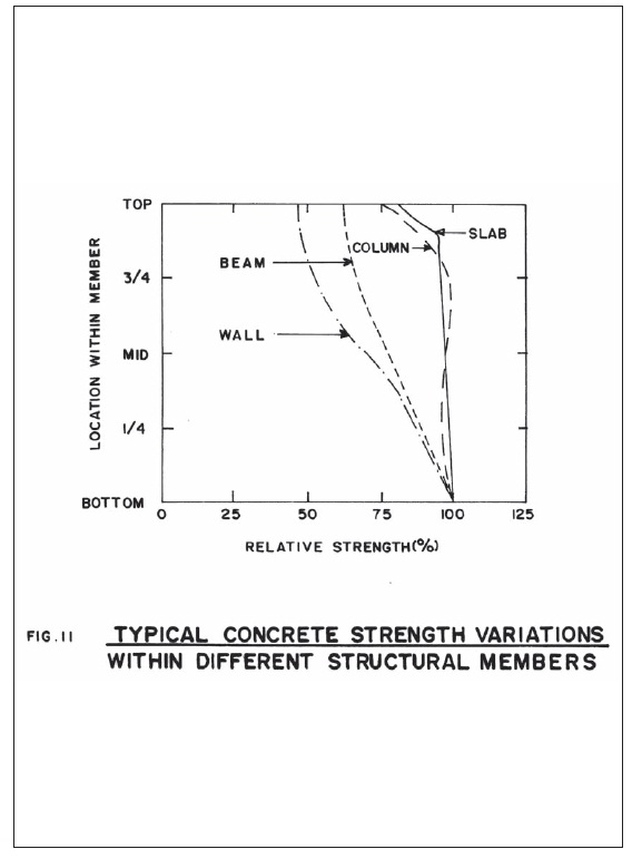
When deciding on the location of a test within a structure it is important to realise that the strength of concrete can vary significantly within that structure. Fig.II. The reason for the variation is related to the migration of water towards the top of the lift during compaction. Note that Specification Compliance Testing will require, in general, that results reflect the average insitu conditions. On the other hand, Serviceability or Adequacy Testing will require results for weakest, most severely damaged or critically stressed regions.
Test and Inspection Techniques
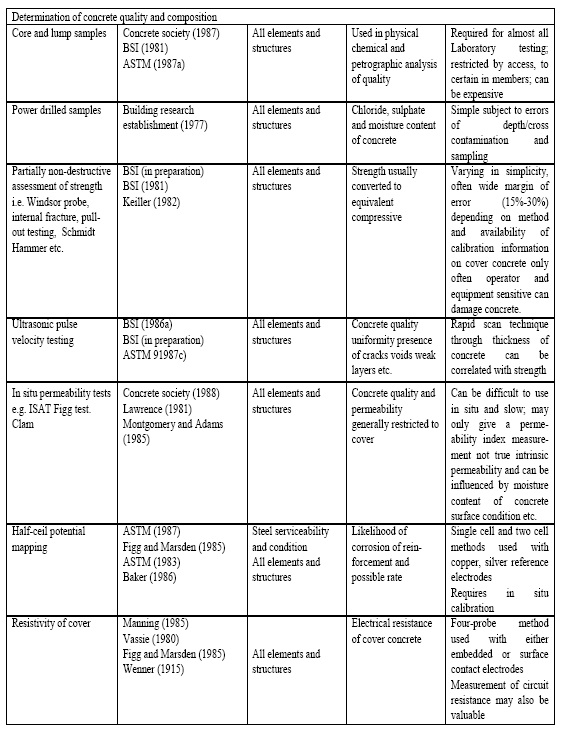
Test and inspection techniques are briefly reviewed under the following headings and in the table at the end of the Appendix.
Visual Surveys
Useful aids include photography, notes, tapes, computer data recorders, pro-forms sheets, check lists.
Sounding surveys
To detect incipient spalls and delaminations over reinforcement in concrete, loose bolts in steel fabrication. Techniques vary from simple hammer to proprietary flails (chains) for concrete decks. Although primarily an aural method the US Federal Highway Authority have developed a method of doing this electronically for bridge decks with a trolley mounted apparatus. May have depth limitations, only detecting surface defects 75 mm to 100 mm deep.
Covermeter Surveys (BS 1881)
Situations often arise on site where it becomes necessary to check the location and cover to the reinforcement in an existing structure. Gamma radiography is one method used to locate reinforcement, however a much cheaper and simpler alternative is to use an electromagnetic covermeter. This test is covered in BS 4408 Pt. 1 and consists essentially of an electromagnet powered by a 9- volt battery. The search head is passed over the concrete and the magnitude of the reading on the galvanometer indicates the depth of cover to the steel. Although the test is simple to carry out, care is required with operation and interpretation of results. Cover to reinforcement is one of the main parameters in concrete durability. Covermeter surveys can:
• Locate main and secondary reinforcement, bar size spacing and cover.
• Determine minimum cover and variability.
• Locate reinforcement or pre-stressing strand for either purpose of assessment calculations, or for avoidance during core sampling.
Gamma Radiography
This method, covered by BS 4408 Pt. 3 is performed by placing a radioactive source on one side of a concrete member and a photographic plate on the other. Its use is restricted to locating reinforcement or areas of poor compaction or for locating voids in concrete and grouted tendon ducts. This is a specialist technique needing stringent safety precautions with little scope in Nepal.
Thermography, Acoustic Emission, Radar
Specialist investigative techniques yield information on structural integrity. Refer to BS 1881 Pt. 201 for advantages and disadvantages.
Dynamic Response/Vibration Technigaues
Used for testing integrity of insitu piles or whole structures. With piles this usually involves striking the head of a pile with a hammer and measuring the dynamic response. Where structures are concerned excitation is normally provided using vibrators clamped to relevant parts of the structure. The dynamic structural response is then monitored using sensitive accelerometers. Both techniques require the use of sophisticated expensive equipment together with skill and care in carrying out the tests and interpreting the results.
Rebound Hammer
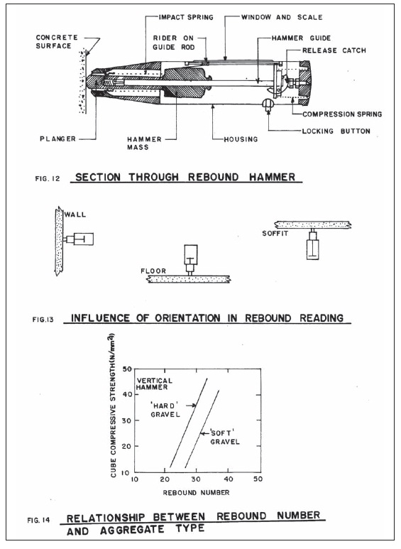
The test method is covered by BS 4408 Pt. 4 and essentially it works by measuring the rebound of a spring controlled hammer. Fig.12. The test is sensitive to orientation of the hammer, Fig. 13. and to local variations within the concrete. To overcome this it is recommended to take the average of a number of readings ( between 9 and 25 over an area not exceeding 300mm by 300mm). The test only measures the surface properties of the concrete and it is therefore very difficult to derive a relationship between strength and rebound number. Apart from surface characteristics the test is also sensitive to other factors such as:
• Aggregate type and content. Fig. 14.
• Cement content
• Moisture content of concrete
• Degree of carbonation (It is not recommended to perform this test on concrete more than 3 months old where high results are likely due to hardening of the surface as a result of carbonation.
The only realistic way to establish a relationship between strength and rebound is to take readings on cubes and crush them. The test has the advantage of being simple to carry out and a large number of readings can be obtained in a short space of time. The equipment is cheap and portable. As a comparative test the accuracy is rated as ± 25%.
Internal Fracture or Pull-out Test
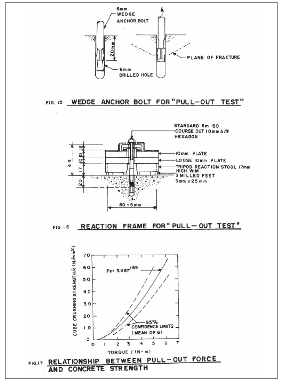
This test was developed by the British Research Establishment in England and measures the force required to pull-out a wedge anchor bolt which has been inserted into a pre-drilled hole. Fig. 5. The procedure involves drilling a 6mm diameter hole into the surface and tapping a 6mm wedge anchor bolt with expanding sleeve into the hole to a depth of 20mm. A load is applied to the bolt through a torque meter and reaction frame until failure occurs by internal fracture of the concrete when the maximum torque reading is recorded. Fig. 6. The mean of six results is usually taken. Calibration specimens should be prepared in the Laboratory (using the same materials as the site concrete) to give the relationship between torque and compressive strength. Fig. 17. An accuracy of ± 28% is claimed, the reasons for the high variability including:
• Localised nature of test
• Imprecise load transfer mechanism
• Variations due to drilling
• Location of large pieces of aggregate near to the bolt.
The test is fairly easy to carry out but does damage the surface of the concrete. Other tests in this category include:
• Windsor Probe -An American test in which the bolt is fired into the concrete and the depth of penetration measured.
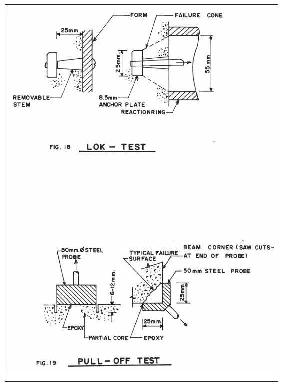
• Lok- Test -Similar to the BRE internal fracture test except that the bolt is cast into the concrete. Fig. 18. (i.e. no drilling required)
• Pull-Off Test -A steel probe is glued onto the concrete surface by an epoxy resin and the force required to pull the piece of concrete off the surface measured. Fig. 19.
Ultrasonic Techniques
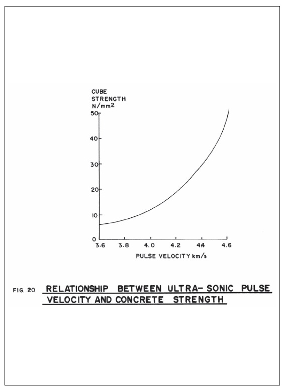
This method measures the speed of an ultrasonic pulse traveling through the concrete from one transducer to another. Fig. 20 gives the relationship between pulse velocity and cube strength. Unless cubes are available which can be crushed after test reading have been taken it is not possible to get direct readings for strength. It is possible to take a large number of readings fairly quickly, the equipment is fairly cheap, easily portable and the test does not damage the concrete in any way. Rather than use the test to assess strength it is perhaps better used to detect voids, crack depth or areas of poor compaction. As with most non-destructive methods it is best used as a comparative tool.
Core Drilling
Core sampling is used to determine concrete quality. Core diameters vary from 40mm to over 200mm. Generally 3 times the aggregate size is specified, however a diameter of not less than 100mm is usually required for strength tests. As well as compressive strength cores can be used for expansion tests for alkali-silica reaction, carbonation and chloride testing, density, porosity concrete composition analysis and information on cracks. (BS 1881 ). It is important to keep full and complete records of core samples taken from the structure for later analysis. Core drilling can weaken the structure and should be carried out only on the authority of the Engineer.
Powder Sample Drilling
Normally taken for the determination of the chloride content of hardened concrete. Powder gradients are taken at various depths when it is suspected that contamination is from an external source, and at depth to give the background level of chlorides. It is also used in determining sulphate profiles, alkali content etc.
Depth of Carbonation
The normal method is to spray a fresh fractured sample of concrete with the inductor. (1% phenolphthalein in alcohol-water base). Phenolphthalein changes colour over the pH range 8.3 to 10 with the red colour visible on concrete above a pH of 9 to 9.5 indicating passivity. Laboratory analysis should be used for an accurate determination of depth of carbonation.
Measurement of Electrical Potentials
Electrical methods for inspection of concrete bridge components include resistance and potential measurements. These methods are particularly useful to detect corrosion of reinforcement.
Crack Meters
These may be in the form of simple comparagauges or more intricate vernier microscopes. The later may be used to inspect the concrete surface inside the crack. The simple crack gauge is an essential inspector's tool.
Measurement of Strains and Deflections
Strains are usually measured by acoustic gauges or electrical resistance gauges. For deflection there are a variety of methods including visual reading dial gauges, precise leveling, electrical transducers or laser techniques. Some equipment is sensitive to thermal strains and care may be needed in the interpretation of the results.
Thickness Testing of Steel Members
Testing for the thickness of steel members can be carried out either by direct measurement or special ultrasonic thickness testing instruments. the latter being accurate down to 0.lmm. This can be particularly useful to determine corrosion loss in a member when assessing remnant strength. Even with no corrosion present the equipment can help to size steel members for records or assessment.
Weld Sizes
A weld fillet gauge can confirm the weld size. Usually this is combined with visual inspection of weld quality.
Flatness Testing of Steel Members
To check distortions and deviation from flatness the normal method is to apply a straight edge to the surface and record distortion and location of test. Steel wire is
used over longer gauge lengths.
Bolts and Rivets
Looseness and movement can be identified by tapping with a hammer. When the bolt is tight the sound penetrates into the full member however the sound is dull when the bolt is loose. A visual inspection identifies corrosion or other deterioration.
High-strength Friction Grip Bolts
These bolts will not be loose. Any check on insitu torque setting will require eventual removal and replacement of the test bolt. A new bolt is always used to replace a test bolt. HSFG bolts are not reused. Bolts must only be removed under engineering supervision and only one bolt at a time removed. Old bolts are inspected for corrosion.
Magnetic Crack Detection
There are a number of different forms of magnetic crack detection which amount to different methods of producing the magnetic field in a test area. All methods indicate the presence of defects on the surface by a magnetic powder which is influenced by the magnetic fields.
Dye Penetration Testing
Used to identify surface defects and cracks in steelwork, particularly welds, the test method is covered by BS4416. Paint is removed and the surface cleaned then sprayed with a low viscosity red dye. This penetrates into cracks or other open defects. After some twenty minutes the dye is cleaned from the surface using a solvent. A dusting of chalk powder is applied which indicates the presence of cracks as a dark stain on the surface.
Hardness Testing
A portable hardness testing apparatus can be used to indicate the approximate strength of steel in a particular area. The surface is prepared to a polished finish and, depending on the type of unit used, a calibrated indentation mark impressed on the steel surface. The relative size of the impressions enable the hardness number to be determined. In the structural steel range hardness numbers below 150 HV are typical of mild steel to BS 4360 Grade 43. Hardness numbers in the range 160 to 200 are typical of higher yield steels to BS 4360 Grade 50.
Ultrasonic Testing of Steelwork
General techniques of ultrasonic testing, described in BS 3923 and BS 4336, normally comprise pulse echo methods in which signals returned from internal flaws are monitored. In particular the technique is used for detection of defects in butt welds and for delaminations in steel plate. There are other variations of ultrasonic testing but all require specialist equipment and skilled operators.
Radiographic Methods of Testing Steelwork
Radiographic methods of testing steelwork are specialist techniques, particularly when used on sites. A more common application is in the laboratory testing of specimens for the approval of welders or weld procedures.
Chemical Analysis of Steelwork
This is used to determine the chemical composition of steel for identification of type or for weld compatibility. Drillings, scrapings or small coupons are cut from an area approved by the engineer for spectrographic analysis.
Load Testing of Structures and Elements
This method entails the assessment of structural response to known applied loading conditions. It can be used either to compare actual behaviour under load with the theoretical predicted performance, or to compare recovery of a structure or element with deflection under load. (i.e. a test pile is a common application of the latter). The loading may be applied to elements, superstructure, substructure foundations or bearings. Applied loading can consist of certified dead weights, water, bagged sand, kentledge, hydraulic jacks or vehicles. (London Busses were used to load test the Tower Bridge in London in 1991- RPT). Water has a number of advantages including cost, accuracy, uniformity of loading and availability.
Response can be measured by deflection dial gauges, load cell, linear voltage displacement transducers, electrical resistance and vibrating wire strain gauge, plastic vernier strain gauge and demec gauge.

